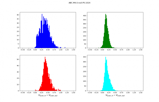
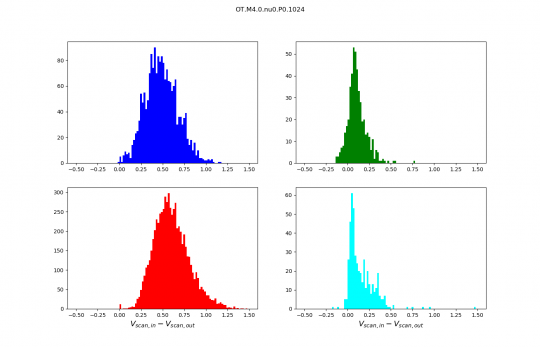
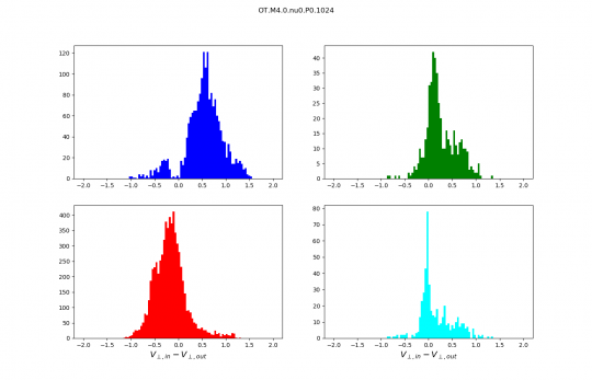
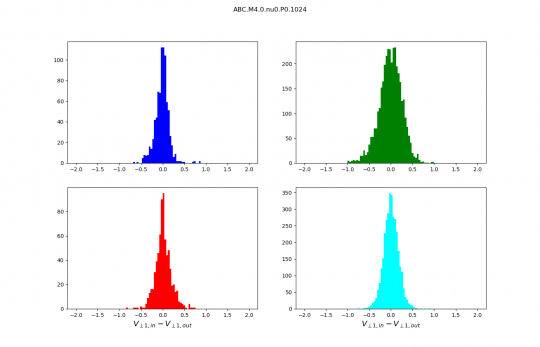
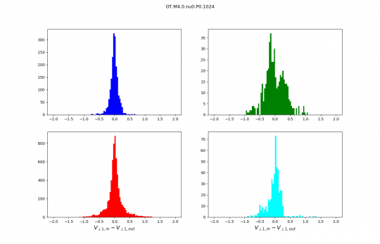
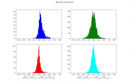
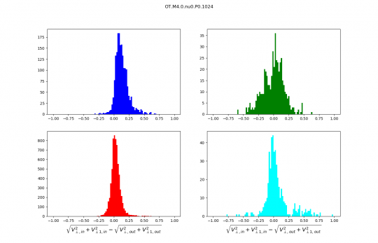
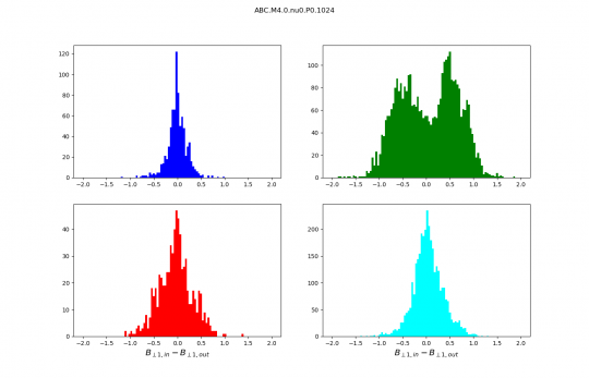
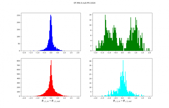
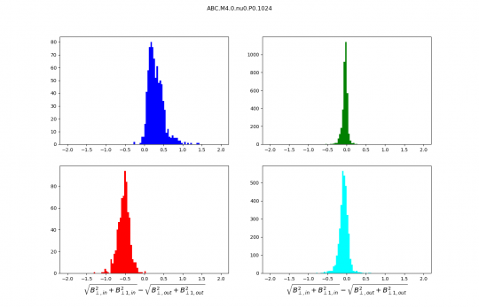
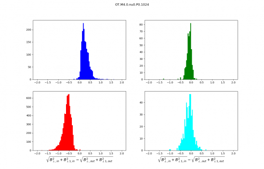
Distributions discussed during the meeting :
Reminder :
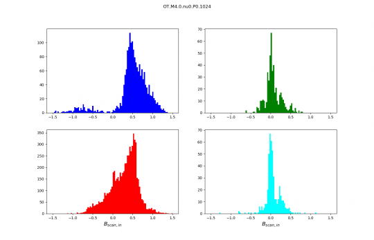
- The sound speed in the code units is 0.25.
- Slow shocks are in blue.
- Fast shocks are red.
- Rotational discontinuities are green.
- Parker sheets are cyan.
Info :
Distributions are no longer normalised, the numbers on the y axis are therefore numbers of scans. I kept only the best identifications we have (purest wave decompositions). It just makes distributions cleaner and analysis simpler.
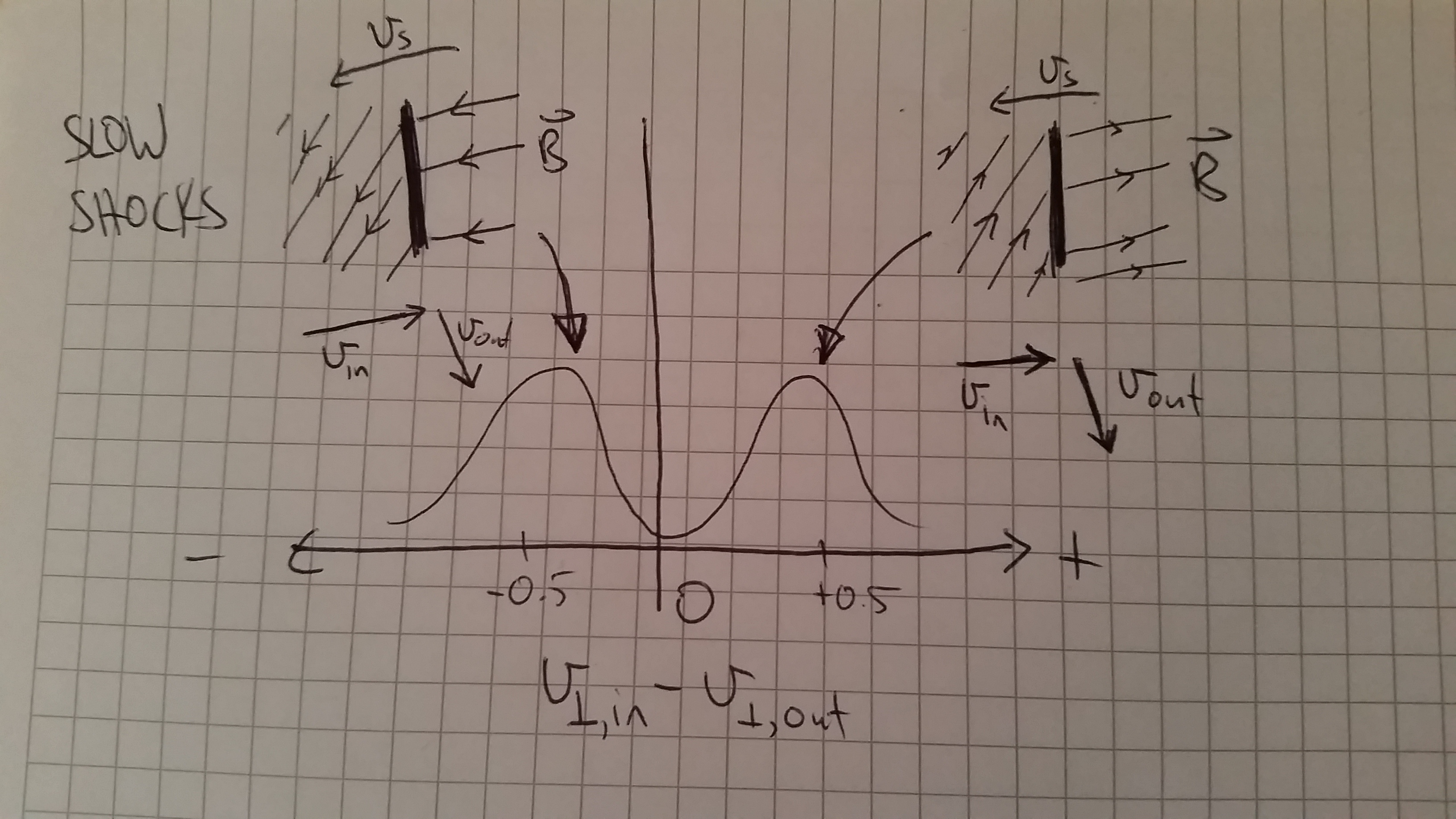
Andrew: Here's a cartoon understanding I have for Thibaud's distributions from today's meeting.
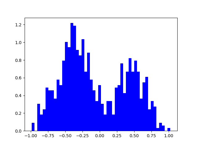
This was for the slow shock (one component) transverse velocity difference (with ABC conditions if i remember correctly). I've drawn cartoon slow shocks travelling from right to left, with magnetic field lines being bent by the shocks. The only difference with the left and right shocks are the directions of the magnetic field. I think the coordinate system defining the transverse directions are based on the preshock transverse magnetic field which is downwards on the left and upwards on the right shock. However the transverse velocity difference doesn't change for these two shocks, so the bi-modal distribution would just come from the two B directions being equally likely. It makes sense to be equally likely to me, so that's why I don't understand the uni-modal (is that a word?) distributions of the OT simulations.
I think i have the left and right shock the wrong way around, the transverse velocity difference is in the same direction as the transverse B on the left shock, so it's difference would be positive.
Pierre: I think what you drew makes perfect sense. And OT would be such that there is a preference on one sign or the other for the Bfield relative to the shock propagation, while ABC has both signs equal. What remains to be understood is how the build up of shocks from the original configuration leads to one or the other situation.
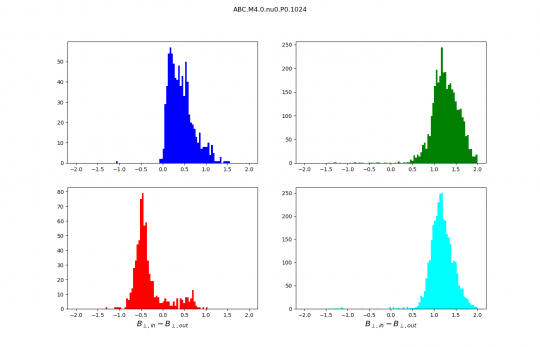
Thibaud: This morning I checked your hypothesis and it seems to be the right one !
I join the PDF of Bscan for slow shocks, that I think is a sufficient proof.
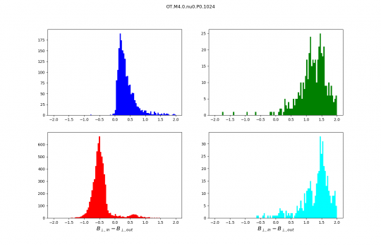
Andrew: Then if what Pierre just said is right the same PDF of Bscan for the OT runs should not be bimodal.
Thibaud: I am actually doing it, but it's a lot of data and my internet connection is not very fast here… I'll tell you if is bimodal too.
[Update :]
Andrew: I made a couple of animations that I think could be helpful.
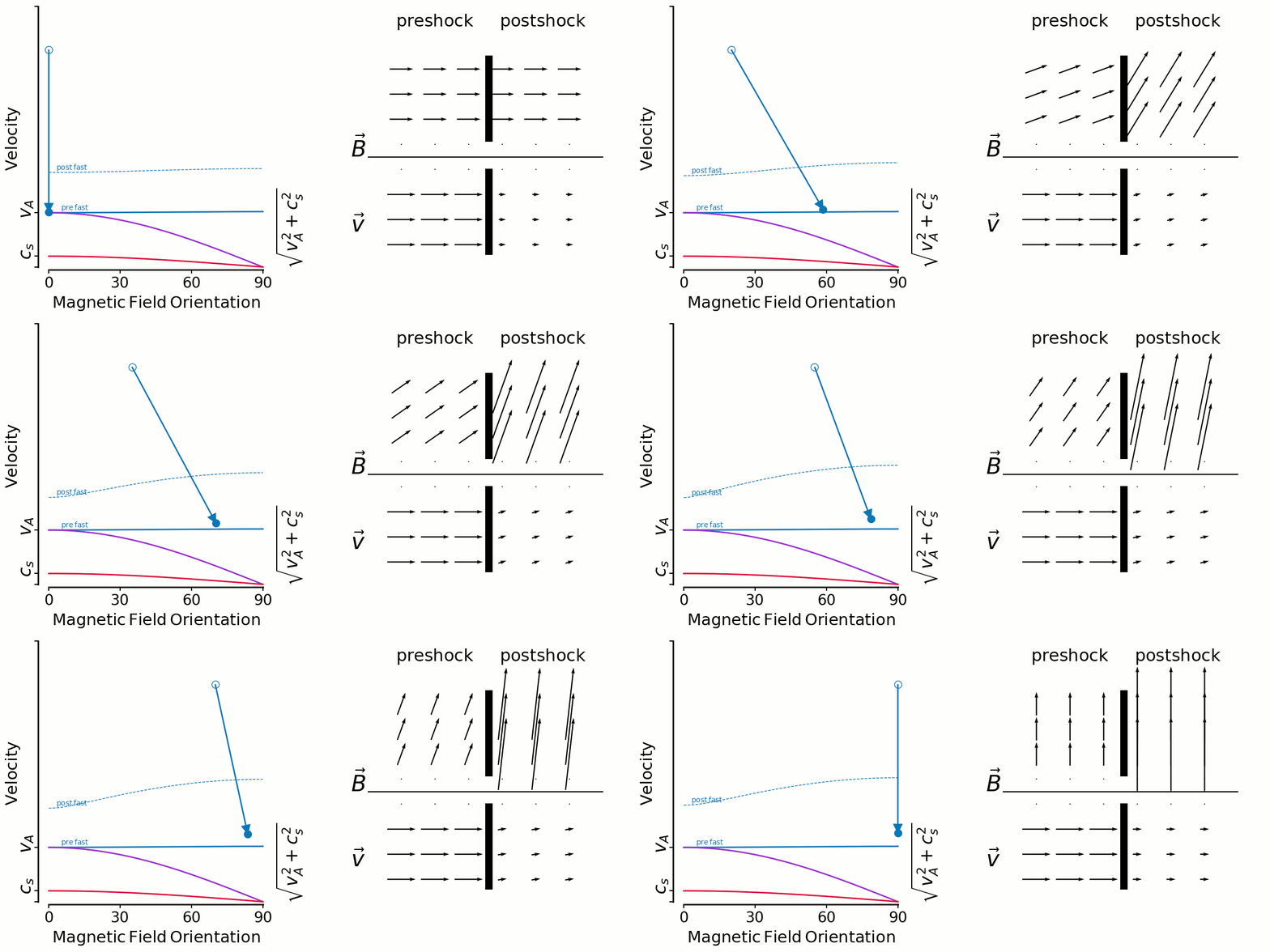
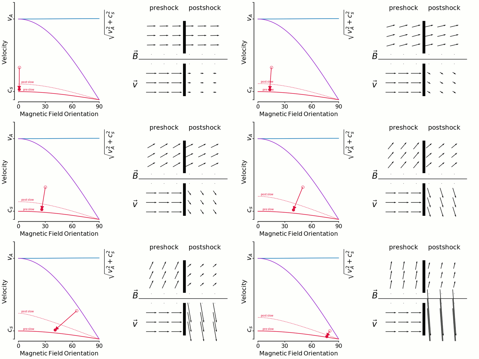
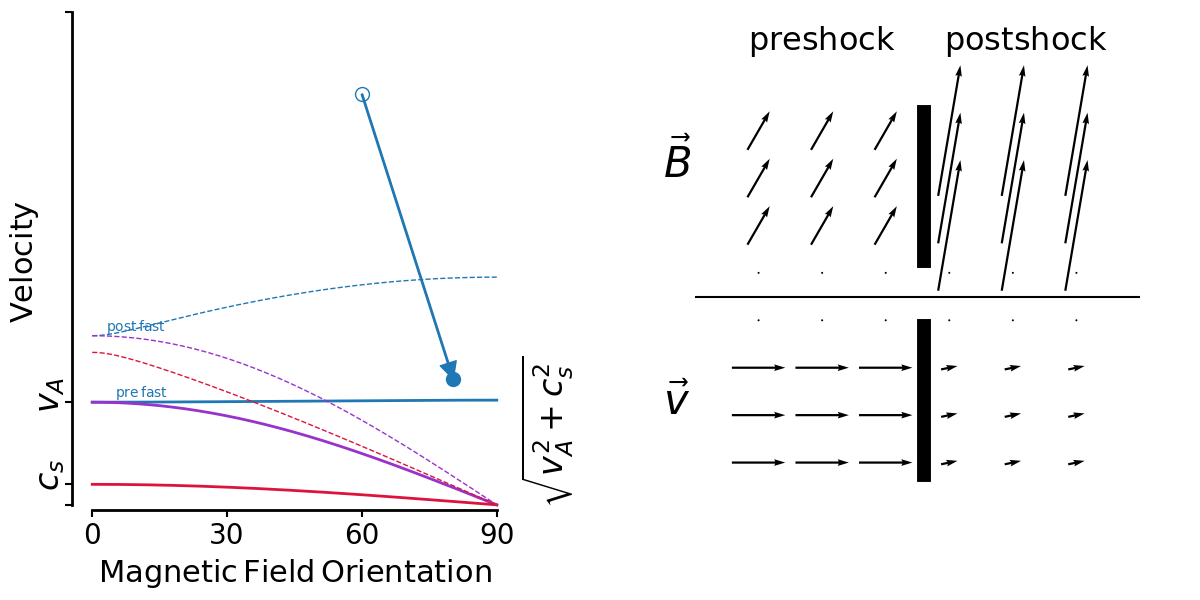
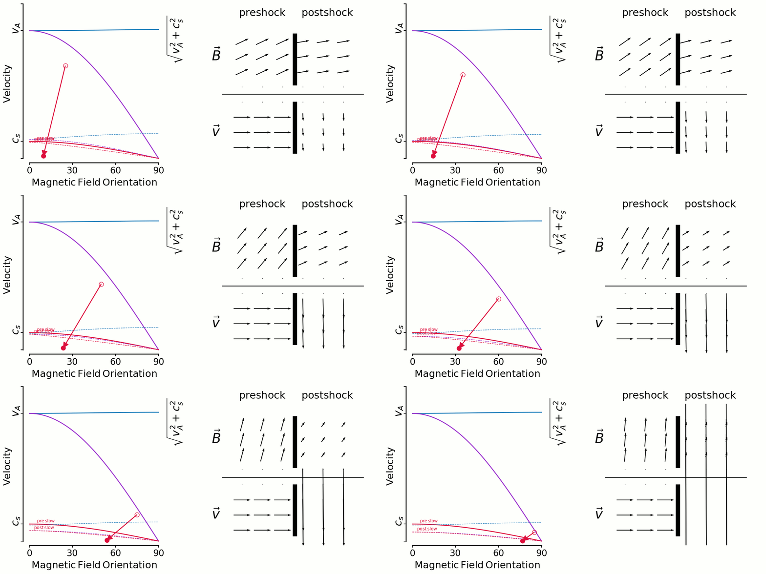
On the left is a kind of shock phase-space diagram. It shows velocity versus magnetic field orientation with respect to the shock normal.
The three unchanging solid lines are the mhd wave speeds—fast, intermediate and slow—calculated with preshock density, pressure and magnetic field strength.
The three changing dashed lines are the wave speeds calculated with postshock density, pressure and magnetic field strength.
A shock is represented by an arrow from an open circle (preshock B orientation, shock velocity) to a closed circle (postshock B orientation,postshock fluid velocity in shock direction).
On the right shows the magnetic field vectors (top) and velocity vectors (bottom) as they are in the pre and postshock gas. I get the postshock values from the jump conditions. There's no shock models being run, just input/output values.
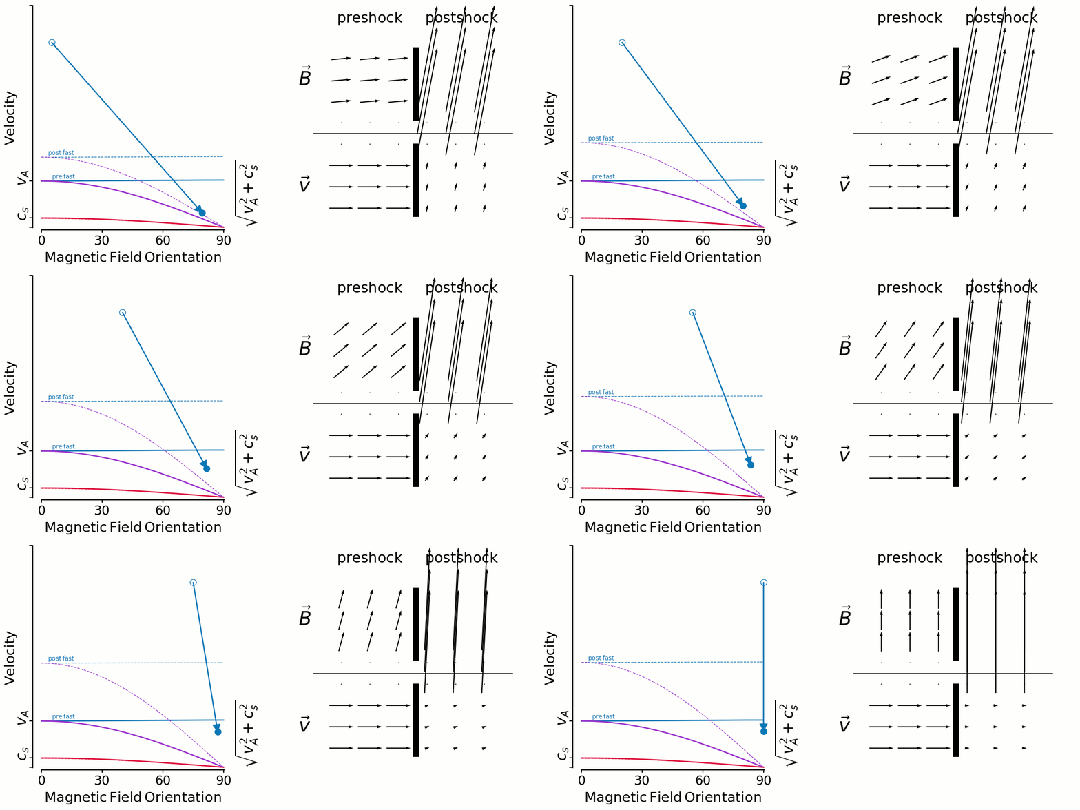
So the first animation shows fast shocks. I'm fixing a shock speed, and sweeping the initial magnetic field direction from 0-90 degrees.
In the context of Thibaud's plots yesterday, you can see in the velocity vectors that there isn't large shear in general.
But this has to be mixed in with the distribution of preshock angles. If shocks are randomly oriented amongst a uniform B field (which seems to be true for ABC but false for OT), the most likely angle is 90 degrees and 0 degrees is non-existant. So it makes sense to me for fast shock shears to be distributed tightly around 0 for the ABC flow.
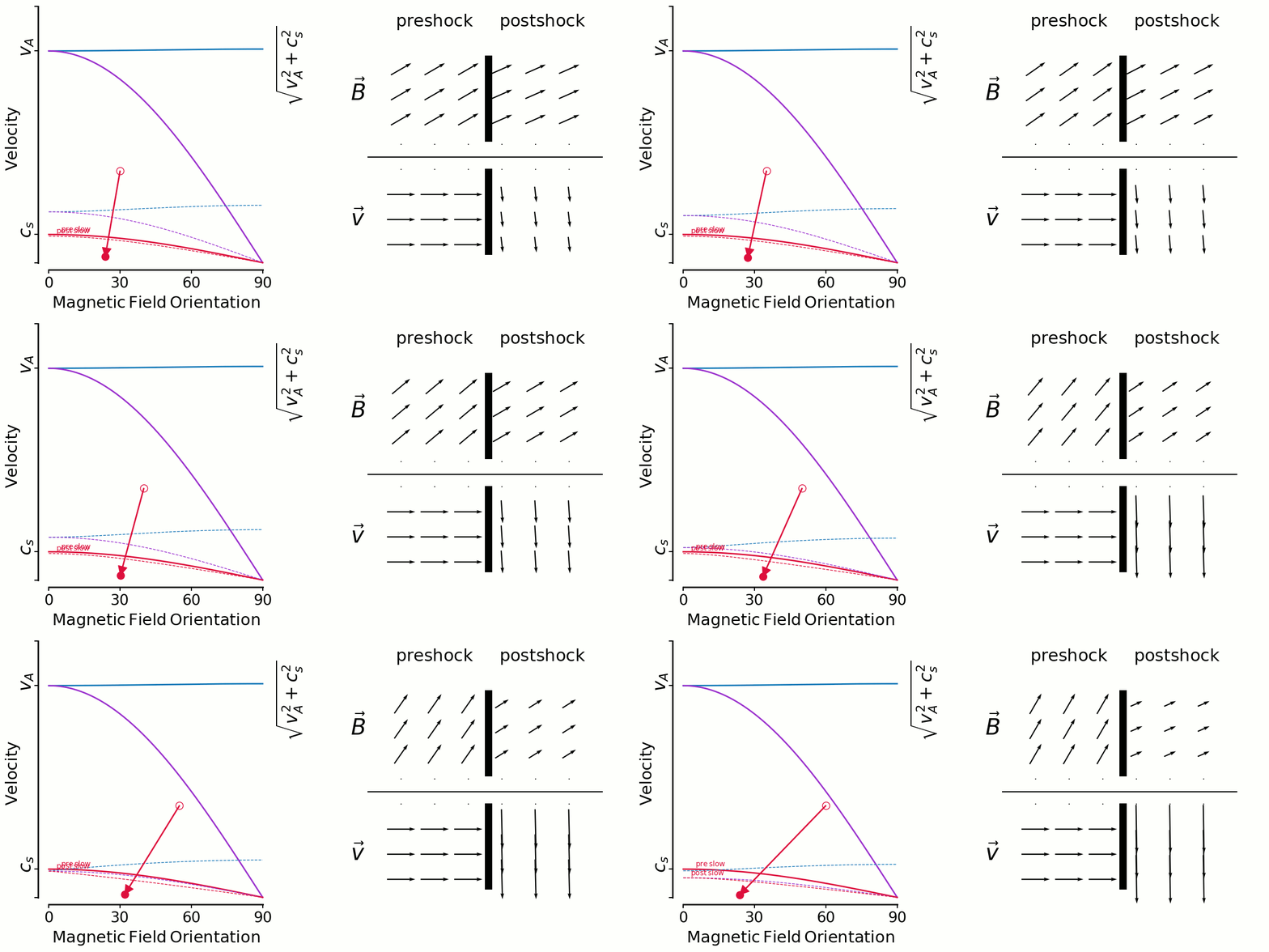
Here's a similar animation for slow shocks. With the large angles more likely (ABC) some amount of shear is likely, and the low shear shocks are unlikely because it's rare to have a shock along the field lines. That's why Thibaud's slow shock shear distributions were low/zero around shear=0, contrary to fast shocks.
But there's an interesting limiting factor for high angles, you can only have lower and lower velocity shocks there, which of course dissipate less and so no longer get looked at by Thibaud.
Edith: Thank you Andrew for your animations. They help a lot and I understand now why the cross-helicity that is very different in the two simulations plays a role.
I do not understand (I think) what you mean by the post-fast and post-slow velocities drawn as dashed lines.
Why do they have a different dependence on the angle at each different angle?
Not sure my question is clear!
I have also questions to Thibaud. I like your color display a lot but I have not succeeded yet to figure out what each of the 15 colors is telling us as soon as more than 2 histograms overlap. Cannot guess the shape of each…
But my question is : why are the Pdfs of v_perp,1 increments so comparable between ABC and OT while those of v_perp so different! I am missing something.
The pdfs of the v_perp modulus differences do not look so different but I cannot tell from the colors Will you send us the same plots with the magnetic field?
Regarding the distribution of the orientations of the scan directions with respect to a fixed direction we expect that this distribution is very broad for ABC and much narrower for OT. Is it true?
Andrew: Your little question has revealed something important actually.
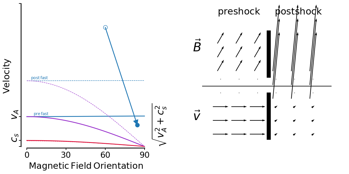
First, the dashed lines labelled post-fast/slow are signal speeds computed the in post shock gas, which now has a different density, pressure and magnetic field strength and so the all the signal speeds are different. Here's a fast shock with all 3 post-shock signal speeds plotted too:
So whenever I see a curvy fast-wave speed (as opposed to flat like in the preshock) I know that means the alfven and sound speed are close.
But why is the sound speed changing? Because I computed adiabatic shocks, when in fact I think I should have been doing isothermal.
Here's the same shock with adiabatic index set to 1:
In isothermal shocks the compression is much stronger and so the magnetic field strength is stronger, and thus the tension is stronger and so the shear is stronger.
So here are those previous animations but for isothermal shocks
The story isn't really any different I think.
And also slow shocks with not constant speed but vs always 80% the intermediate speed to always remain below it's limit.
At the very high angles the relative shear blows up. I say relative shear because the velocity vectors are normalised to the shock velocity. So while the shear looks like it's growing, the shock velocity is in fact decreasing, and as said in the previous email these ever decreasing mach numbers are no longer interesting because they don't dissipate much.
Pierre: Would it be possible to show velocity shears in units of the sound speed in these diagrams ?
This way we don't have to factor out the relative proportions with respect to shock speed, and we can compare more directly to Thibaud's results.
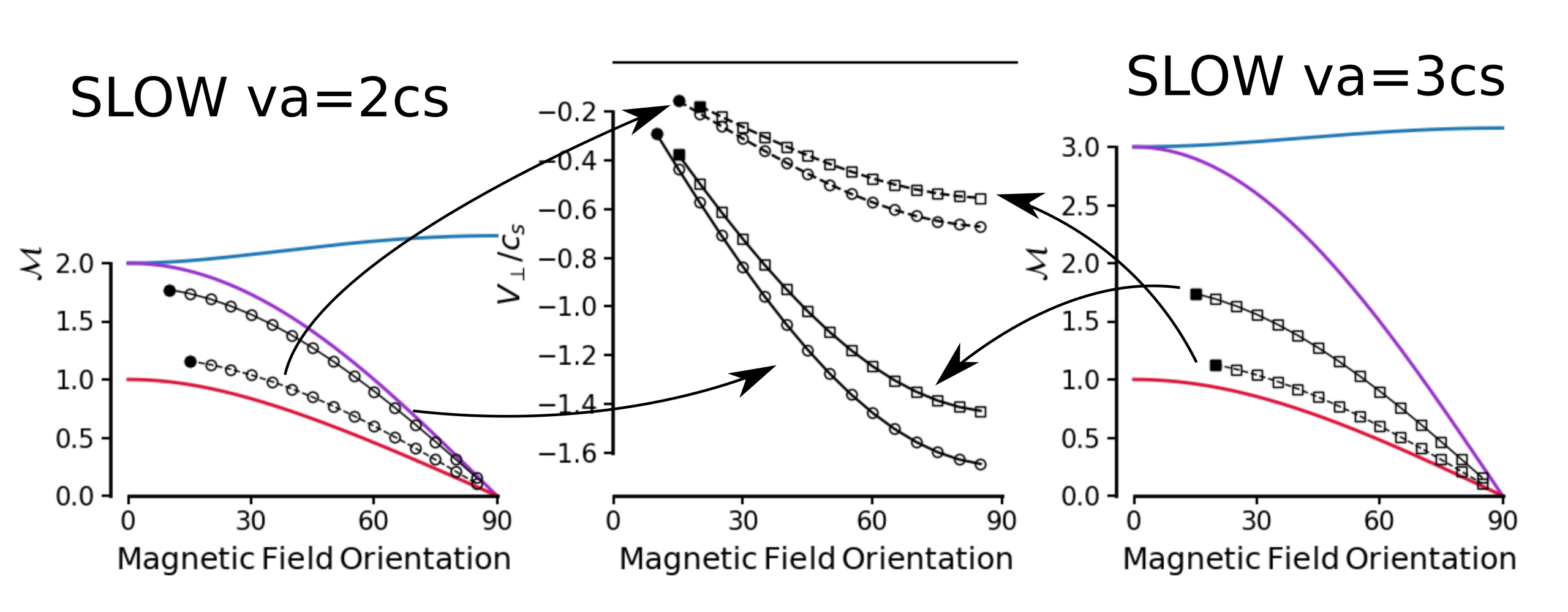
Andrew: Ok I think I've done this. Here are sweeps of slow and fast shock parameter spaces, with transverse shift velocities relative to the sound speed. Left shows the phase speeds tuned to allow slow shocks with mach numbers up to ~2.5 Right shows phase speeds tuned to allow fast shocks with mach numbers 1.5 and 2 (I wanted to keep the mach numbers low because I think you guys were finding very low mach numbers in the simulations, correct me if i'm wrong here) Middle panel shows the transverse velocities caused by the shocks, with circles for slow shocks and squares for fast shocks and line styles matching their source.
Here's the same kind of thing, but for fast shocks with 2 different magnetic field strengths: vA = cs and vA = 0.5cs
This shows the shears are weaker when you reduce the field strength, which I guess is obvious because the shears are caused by magnetic tension.
And for slow shocks, here are two sets of identical shock velocities (vs=1.2*cs*cos(theta) and vs=1.8*cs*cos(theta)) but on the left we have a “weak” magnetic field such that vA = 2*cs and on the right a “strong” field such that vA = 3*cs.
So as usual higher shock velocities lead to higher shear velocities. But for a fixed shock velocity lower magnetic field strength gives higher shear velocity.
Magnetic field increments
